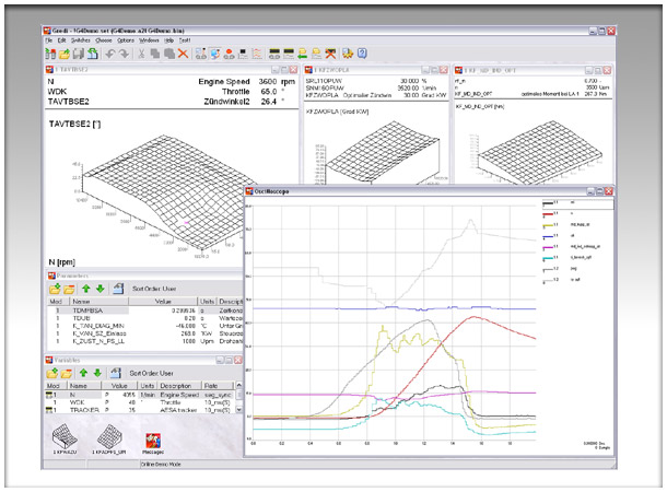
| All-in-one
All major functions required by an application
engineer are integrated into a single intuitive framework:
- Numeric and graphic calibration of
ECU maps and parameters
- display, recording and evaluation of simultaneously acquired
ECU internal and process data
- transfer, comparison and documentation of calibration
data (changes)
- flashing of ECU program and data memory
- monitoring of ECU communication.
|
| |
 |
| |
| DriveRecorder |
| |
| The DriveRecorder is like a flight
recorder for your development or durability vehicle. Setup
is extremely simple: Just select the ECU data elements you
wish to record by double-clicking in online mode, and recording
starts instantly. MCS400 saves the ECU data elements to local
flash memory on a rolling data log - the PC can be disconnected
and reconnected at any time. You can then upload the data
and, evaluate and archive within Gredi V4 just as you would
conventional recorded data. |
| |
| Lower Total Cost of Ownership |
| |
One of the most attractive features
of Gredi V4 is that when you purchase MCS400 you receive Gredi
V4 as part of the package. There is even no expensive maintenance
contract, you get free software updates, free support via
email or phone and there are no software license fees for the standard
Gredi V4 software. Gredi V4 is evolving all of the time, with
new features being added and existing features being enhanced.
Customer specific extensions are possible, please contact
us in order to receive a quote. |
| |
| Slim and easy to use |
| |
| Gredi V4 runs under Windows 98,
NT, 2000 and XP and is designed to be as easy to use as possible.
Overwhelming featurism is replaced by a slim and smart function
set. Most configuration is done automatically, repetitive
tasks are simplified by retaining the previous system state.
Build-in expert knowledge tries to shield the application
engineer from tedious tasks. |
| |
| Responsive |
| |
| Launching Gredi V4, initialising
MCS400 and closing Gredi V4 all take just seconds. Gredi V4
is designed with large multi-ECU projects in mind, supported
by MCS400 as a stand alone computer with it's own Real Time
Operating System. |
| |
| Sophisticated error handling |
| |
| With Gredi V4's sophisticated
error handling, if your ECU resets, Gredi V4 will restore
the calibration data to the ECU. When Gredi V4 compiles your
ECU description files, if values are out of range or incorrect,
Gredi V4 will warn you and show you the line where the error
occurs. Error checking is performed strictly and self-healing
is done wherever possible, but unrecoverable errors are reported
directly to prevent fuzzy system behaviour. |
| |
| Network functionality |
| |
True network compatibility with
plug and play IP Configuration.
As the MCS400 can act as a DHCP server or client and with
our Plug and Play IP configuration, integration into your
company network should be simple. Or you can plug it straight
into your PC network port and because of the MCS400 feature
of auto selecting MDI / MDIX crossover, you don't even have
to change your network cable. You can even assign a specific
IP address to the MCS400 allowing the user to not only operate
the MCS400 over the company LAN but also over WAN connections,
i.e. over the Internet. |
| |
| MCS Navigator allows easy
Point & Click MCS Selection |
| |
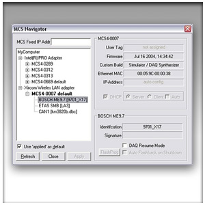 |
To simplify networking Gredi
V4 has a graphical navigation window that allows you to identify
all MCS400's and ECU's connected to the network for point
and click selection. |
| |
| Industry Standards supported |
| |
Gredi V4 natively supports open
industry standard ASAP2 (ASAM-MC2) ECU description (.a2l)
files, as well as Intel Hex (.hex) and Motorola S-Record (.s19)
calibration data files.
Calibration data listings can be exported as DAMOS Format
(.dcm) files.
CAN database (.dbc) files are natively supported for ECU communication
monitoring.
Gredi V4 and DriveRecorder recordings can natively be stored
as Measure Data Format (.mdf) files, which provides a convenient
way of archiving data and a is a well established means of
data exchange in the automotive industry.
Gredi V4 provides high-level access to ECU data for e.g. test
bed systems via it's build-in ASAP3 Host Coupling Interface. |
| |
| Legacy support |
| |
| Gredi V4 still natively supports
the ECU description (.rob), raw calibration data (.bin) and
recording (.rec) files that previous Gredi versions used.
An upgrade path is provided by export features allowing exporting
of rob descriptions
to ASAP2 format and rec files to Measure Data Format. |
| |
| XY Diagram |
| |
"Power Curves" and other non
time based charts can be built using the XY Diagram, the XY
Diagram is also useful as a real-time working point monitor.
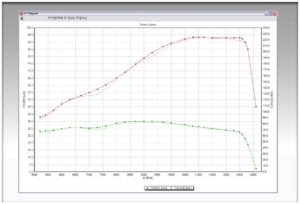
The chart is build by sequentially driving the engine on the
testbed through all workpoints and triggering the
measurement for ever workpoint.
The trigger channel controls the sampling and storing of
averaged online values into the XY Diagram. Modes of
operation are:
- Start manually, store value after averaging time.
- Start via trigger channel, store value after averaging
time.
- Trigger channel starts and stops averaging, store value
afterwards.
- Continuously store values after averaging time.
Erroneous data points can be easily removed.
The "Load Reference File" allows a before/after comparison
of e.g. optimizing attempts.
Up to 4 Y-axes are possible |
| |
| Calibration Data Listing function |
| |
| Calibration data listing allows
you to create readable listing files of all or selected elements
for documentation and data exchange purposes, mainly exported
to different text file formats. The list of selected elements
can be saved to and read from a disk file. |
| |
| Calibration Data Transfer
function |
| |
| Calibration data transfer allows
you to transfer all or selected elements to a destination
calibration data file for upgrading and merging purposes.
Different ECU description files for source and destination
are allowed and the transfer is made via the physical (engineering)
model, even map dimension changes with linear interpolation
are supported. The list of selected elements can be saved
to and read from a disk file. |
| |
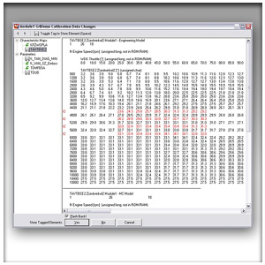
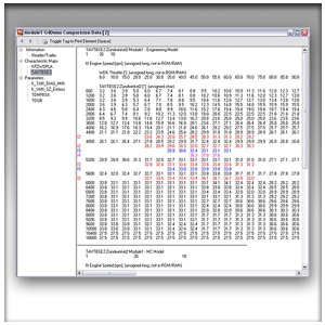
| Calibration Data Compare functions |
| |
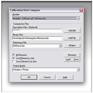 |
Calibration data compare allows
you to visualize the differences between up to four calibration
data files. Different ECU description files are allowed and
the comparison is made in the physical (engineering) model.
The comparison result can be viewed on screen, printed or
exported to different file formats. The list of selected elements
can be saved to and read from a disk file. |
| |
| Another kind of compare function
jumps in whenever calibration data changes are present and
you are about to close Gredi V4: You can review all changes
made and accept or decline each change individually on a per-element
basis. |
| |
 |
|
| |
| Simultaneously talk to 20
target devices (modules) |
| |
| With Gredi V4's ability to interface
to 20 target devices on 2(4) CAN busses and 2 Multi Mode Serializer
Ports simultaneously, you can control, calibrate and monitor
not only ECU's, but pseudo ECU's i.e data acquisition sub-systems
and Rapid Prototyping Modules (RPM). |
| |
| ECU communication monitoring |
| |
| ECU communication can be monitored
either as trace dump or in sorted listview style. By means
of CAN database (.dbc) files, raw communication packets can
be decoded into easy readable form. |
| |
| ECU flash programming function |
| |
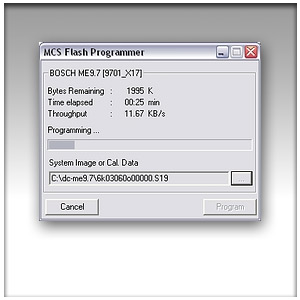 |
The flash programming window
shows ECU data and Flash file data as well as the progress
monitor. |
| |
 |